Lesson 1 of 2 in On the workbench
Using a multimeter
By Mihai Dumitru · · · 6 min read
On this page
A multimeter measures voltage, current and resistance, and it is the first tool worth buying when you start building circuits. It is also easy to use wrongly, because each kind of measurement needs the probes in a different place. This page explains where they go and why. It assumes you know Ohm's law and the difference between series and parallel.
The sockets and the dial
A typical multimeter has a black lead in the socket marked COM, which stays there for everything. The red lead goes into the socket marked V Ω (often also mA) for voltage, resistance and small currents. Many meters have a separate socket marked 10A for large currents. The dial selects what you measure. On a manual meter you also choose a range: start with the highest range and turn down until the reading is clear. Autoranging meters do this for you.
Practice with a multimeter
The circuit is a 9 V battery, a 470 Ω resistor and a red LED. Set the dial, choose where the probes go and see what the meter would show.
Dial
Probes
Meter shows
7 V
This is the right way to measure it. That's the real value for this part.
Measuring voltage
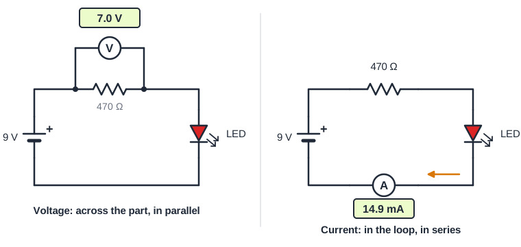
Voltage is measured across a part, with one probe on each side of it, while the circuit is powered. The meter is then in parallel with the part. In volts mode the meter lets almost no current through, so it doesn't disturb the circuit. In the practice circuit, the 9 V of the battery splits into about 7 V across the resistor and about 2 V across the LED.
Measuring current
Current is measured in the loop. You open the circuit at one point and put the meter in the gap, so all the current flows through the meter. The meter is then in series with the circuit. In current mode the meter is almost a plain wire, so it doesn't change the current it measures. In the practice circuit it shows about 14.9 mA, which matches Ohm's law: (9 − 2) ÷ 470.
Because the meter is almost a wire in current mode, putting it across the battery or across a part is a short circuit. The current inside the meter jumps and its fuse blows, or worse. If your readings suddenly stop working in current mode, check the fuse.
Measuring resistance
Resistance is measured with the power off. In ohms mode the meter sends its own small current through the part and measures the voltage it produces. A powered circuit interferes with that, gives meaningless readings and can damage the meter.
Ideally the part should also be out of the circuit, or at least have one leg disconnected. Otherwise other parts connected in parallel with it change the reading. Resistance is also only meaningful for resistive parts. An LED or a diode gives OL (out of range) or a changing number, and a battery should never be measured in ohms mode.
Two more useful settings
- Continuity. The meter beeps when the two probes are connected through a very low resistance. It is the quickest way to check a wire, a fuse, a solder joint or a switch, always with the power off.
- Diode test. The meter pushes a small current through a diode and shows its forward voltage, about 0.6 V for a silicon diode in the right direction and OL in the reverse direction. Many meters light up an LED faintly in this mode, which is a quick way to check its colour and direction.
A good habit
Before trusting a reading, check it against what you expect. If Ohm's law says a resistor should drop about 7 V and the meter shows 0.2 V, the circuit, the probe placement or the meter setting is wrong. The habit of predicting the reading first is what makes a multimeter useful for finding faults.
Check yourself
Where do the probes go to measure the voltage across a resistor?
Show the answer
One probe on each side of the resistor while the circuit is powered, with the meter in volts mode. The meter is in parallel with the resistor.
Where does the meter go to measure the current through an LED?
Show the answer
Open the loop at one point and put the meter in the gap, in current mode, so all the current flows through it. The meter is in series with the LED.
Why must the power be off when you measure resistance?
Show the answer
In ohms mode the meter sends its own small current through the part. Voltage from the circuit would upset that measurement, give a meaningless number and can damage the meter.
Your meter suddenly reads nothing in current mode. What is the most likely cause?
Show the answer
A blown fuse inside the meter, usually from measuring voltage while the red lead was still in the current socket.