Lesson 3 of 6 in On the workbench
How to read a circuit diagram
By Mihai Dumitru · · 7 min read
On this page
A circuit diagram, also called a schematic, shows which parts a circuit uses and how they are connected. It does not show what the parts look like or where they sit on the board, only the connections. Once you can read one, you can build circuits from books, datasheets and websites. The first circuit page showed a few symbols. This page collects the common ones and explains the conventions around them.
The symbols
Each part has its own symbol. The chart below shows the ones used in this course. Some parts have two common styles: a resistor is a zigzag in American drawings and a small rectangle in European ones, so you will see both.
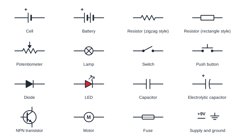
A few details carry meaning. On a battery or cell, the longer line is the positive terminal. On a diode or LED, the triangle points in the direction current can flow, and the bar marks the cathode. On an electrolytic capacitor the curved or hollow plate, or a small + sign, shows which side must go to the more positive voltage. The arrow of a transistor sits on the emitter.
Lines and dots
A line is a wire, or any conductor, such as a copper track on a circuit board. Its length and shape don't matter: a long line and a short one are both just a connection. What matters is what it connects.
- A dot where lines meet means they are connected.
- Lines that cross without a dot are not connected. One wire simply passes over the other.
- Careful drawings avoid four-way junctions and draw two T-junctions instead, so that a missing dot can't cause confusion.
Supply and ground labels
Larger diagrams often leave out the battery. Instead, the top of the circuit ends in a short bar labelled with the supply voltage, such as +9V or VCC, and the bottom ends in the ground symbol, a set of shrinking horizontal lines. Ground is the reference point that all other voltages are measured from, usually the negative terminal of the supply. Every point marked +9V is connected together, and every ground symbol is connected together, even when the diagram doesn't draw the wires.
By habit, diagrams put the positive supply at the top and ground at the bottom, so current flows downwards through the parts. Signals usually travel from left to right: inputs on the left, outputs on the right.
Names and values
Each part gets a short name: R for resistors, C for capacitors, D for diodes, LED for LEDs, Q for transistors and U or IC for chips, numbered R1, R2 and so on. A parts list then gives the exact type of each. Values are often written with the unit letter in place of the decimal point, because a printed dot can get lost: 4k7 means 4.7 kΩ, 1M5 means 1.5 MΩ and 2R2 means 2.2 Ω. Capacitors use the same trick, so 4n7 is 4.7 nF and 100u is 100 µF.
From diagram to circuit
To build a circuit from a diagram, go through it one connection at a time. Pick a point, list every part that touches it, and make sure exactly those parts are joined in your circuit. Tick each connection off on a printout as you go. A breadboard makes this easy, because every row of holes is one connection point.
Check yourself
Two lines cross on a diagram without a dot. Are the wires connected?
Show the answer
No. Lines that cross without a dot are not connected. A dot is needed to show a connection.
What does a resistor labelled 4k7 measure?
Show the answer
4.7 kΩ, which is 4,700 Ω. The k takes the place of the decimal point.
How can you tell which terminal of a battery symbol is positive?
Show the answer
The longer line is the positive terminal.
A diagram has three ground symbols in different places. How many wires do you need to connect them?
Show the answer
They are all one connection point, so they must all be joined together, usually to the negative terminal of the supply, even though the diagram doesn't draw the wires.